3.3.4 Quantum full adder
The add cirucit use CNOT and CCNOT circuits so it is important to know the output state of the target qubit of CNOT and CCNOT.
CNOT gate acts on two qubits, A as control qubit and B as target qubit.
The output state of CNOT = \(|A>|A \oplus B>\)
It is easy to verify it through true table. When A is |0> as control qubit, the output of B(target qubit) is unchanged. When A is |1> as control qubit, the output state of B(target qubit) flips. Therefore, the output state of target is XOR between the state of A and B.
CCNOT gate acts on three qubits, A and B as control qubits and C as target qubit.
The output state of CCNOT = \(|(A \cdot B) \oplus C>\)
We can see A and B as one qubit(\(A \cdot B\)) to control the target qubit so it is the same as CNOT gate.
The quantum circuit of full adder as follows:
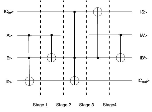
We derive the math expression of \(C_{out}\) and S seperately.
From the equation above, we can see the expression state of |S> equals the math one of S of a full adder.
However, the expression of \(C_{out}\) is different from the one of a full adder. We can simply the expression to verify that they are the same one.
We can see the expression of \(|C_{out}>\) equals the \(C_{out}\) of a full adder. Therefore, the quantum full adder circuit can have the function of adding two qubits with carry.
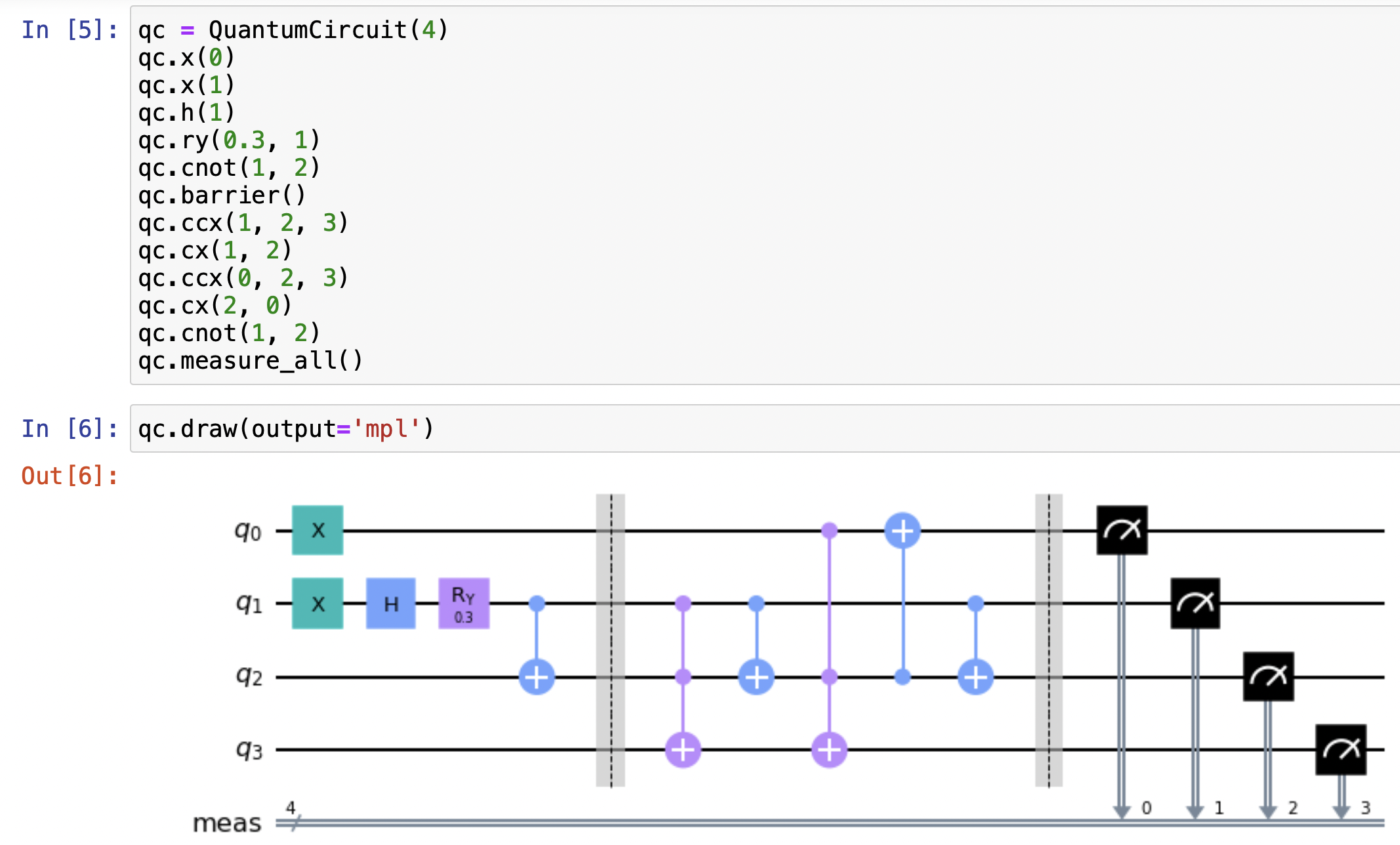
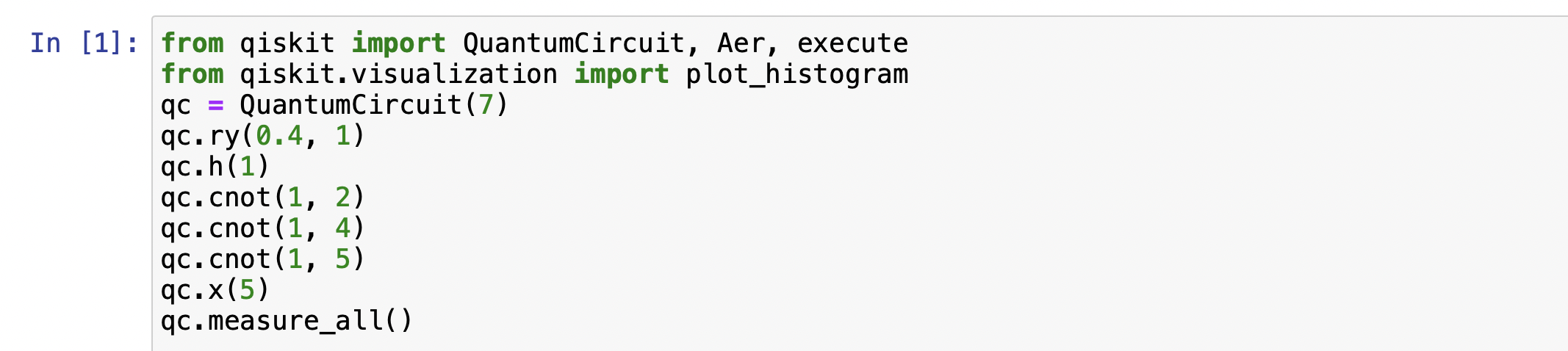
For example, before we use the quantum full adder, we need to prepare the input qubit for the value we want to compute. For example, when A = 0, B = 0, Cin = 1 and A = 1, B = 1, Cin = 1, we need to design quantum circuit to satisfy the condition. I used qiskit simulator to make the quantum circuit and got the measurement outcome of the circuit. The quantum circuit as follows:
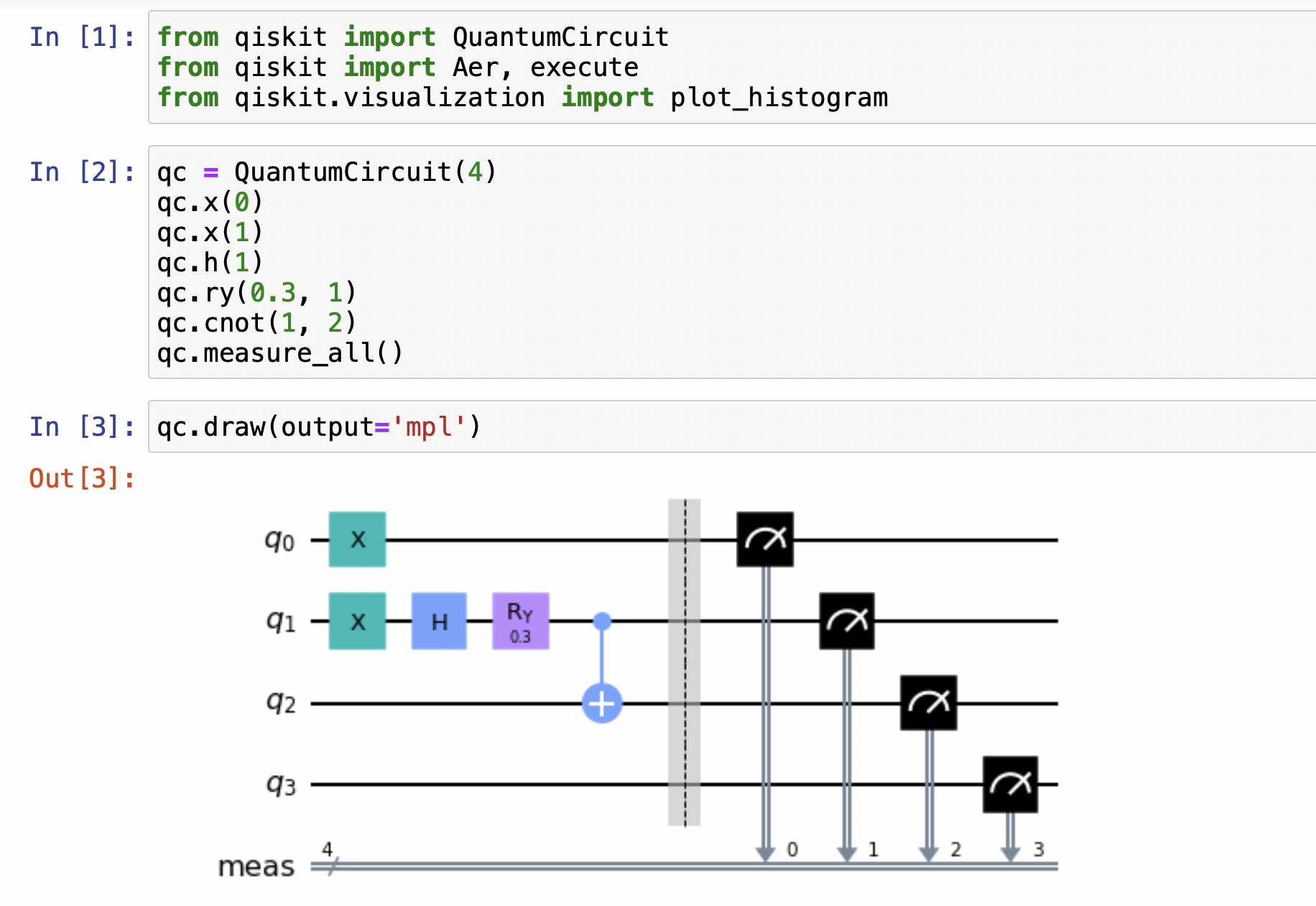
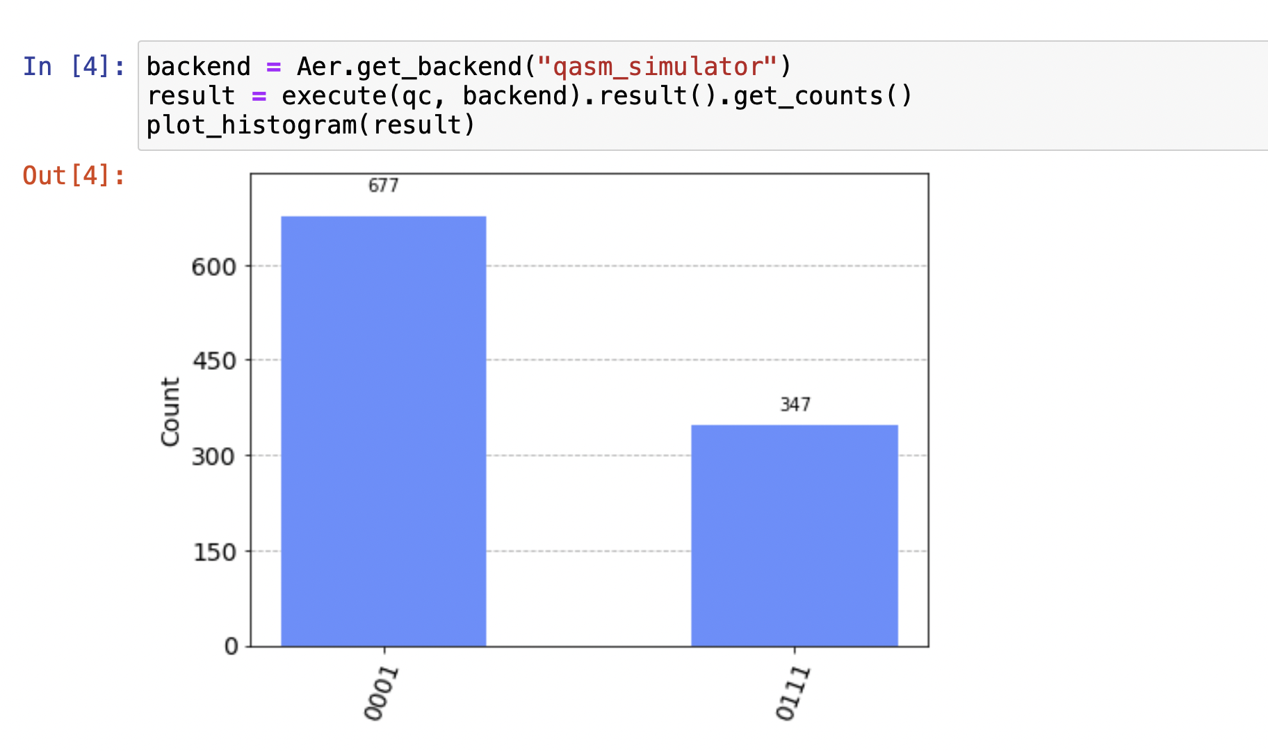
The first qubit |q0> is Cin, the second |q2> and third qubits |q3> are A and B, the last qubit |q4> is |0> as the input qubits. We prepared input quantum states, one is |A> = |B> = |0>, |Cin> = |1>, and the other is |A> = |B> = |1>, |Cin> = |1>. In Qiskit, note the first qubit is the rightest one in the figure. The outcome in the figure is |0001> with the probability with 677/1024, and |0111> with 347/1024.
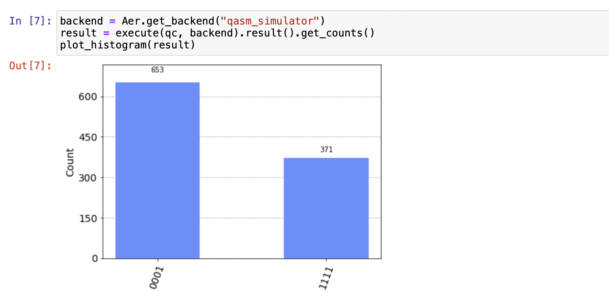
In the figure, from the right to left, the first qubit of the final result is the sum of A and B, the second and third one are A and B, and the last one is the carry.
In the figure, |0001> represents the carry is 0 and the sum of A and B is 1 when A = B = 0, and Cin = 1. Its probability is 653/1024 which is close to 677/1024. |1111> represents the carray is the carry is 1 and the sum of A and B is 1 when A = B = 1, and Cin = 1. Its probability is 371/1024 which is close to 647/1024. It means that the quantum circuit can perform the function of a full adder.
The preceding illustration described a one bit full adder. Now, consider the figure below, representing a two bit full adder composed of two such one bit adders, such as A = 01 and B = |11>. This conceptual framework can be extended to design quantum adders for systems involving multiple bits.
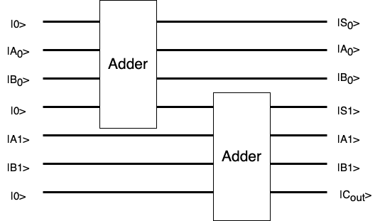
When 01 and 11 are as the input of a two bit full adder, it means that |A0> = |1>, |A1> = |0>, |B> = |1>, and |B>=|1>. The Cout of first adder is as the input Cin of the second adder. The output of |S0>, |S1>, and |Cout> represent the first bit and the second bit of Sum (from right to left), and the carry bit value. The sum of 01 and 11 equals 100 so |S0> = |0>, |S1 > = |0> and |Cout> = |1>.
When multiple qubits add respectively, it only prepares the input qubits in superposition. When the sum of the 11 and 01, it prepares |A0> = |1>, |A1> = |1>, |B0> = |1>, and |B1> = |0>. when the sum of the 00 and 10, it prepares |A0> = |0>, |A1> = |0>, |B0> = |0>, and |B1> = |1>. Therefore, |A0>|B0>|A1>|B1> needs to be |1110> and |0001> in the superposition.


From the outcome of qiskit, qubits are in the superposition with |01100100> and |0000010>(from the right to left in the figure). It illustrates that |A0>|B0>|A1>|B1> is in |1110> and |0001> with the probability of 326/1024 and 698/1024 respectively.
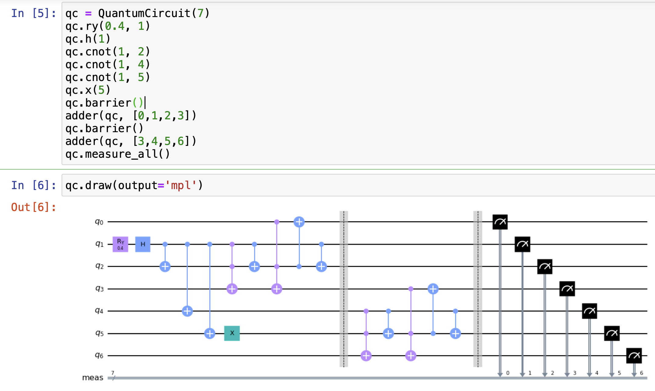
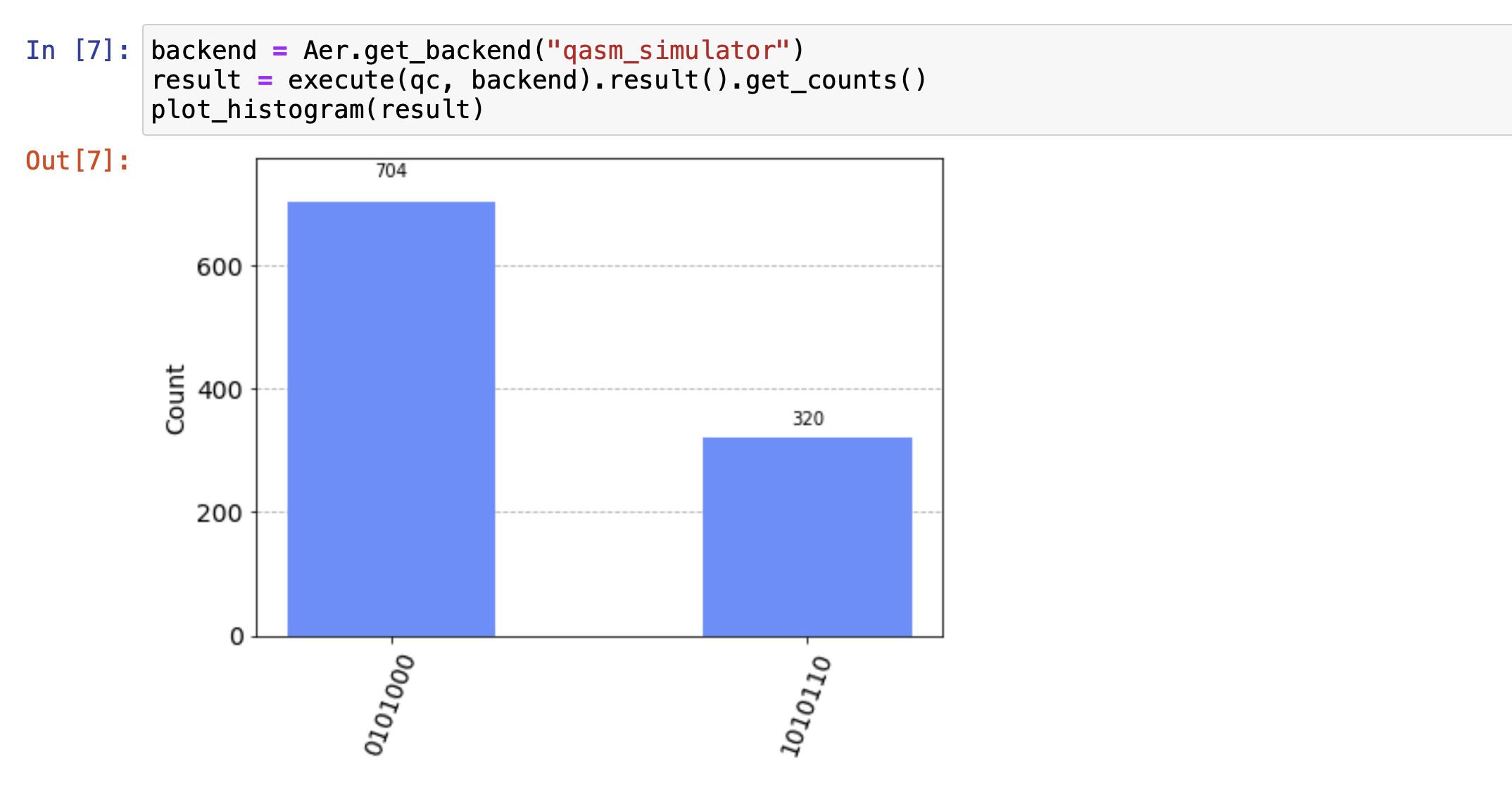
The outcome |S0>|A0>|B0>|S1>|A1>|B1>|Cout> in the figure is |0001010> and |0110101>(from the right to left in the figure).
|0001010> is |S0> = |0>, |A0> = |0>, |B0> = |0>, |S1> = |1>, |A1> = |0>, |B1> = |1>, |Cout> = |0>, so it means the sum of 00 and 10 equals 010.
|0110101> is |S0> = |0>, |A0> = |1>, |B0> = |1>, |S1> = |0>, |A1> = |1>, |B1> = |0>, |Cout> = |1>, so it means the sum of 11 and 01 equals 100.